

Independent control of up to Sixteen Stepper Motors through One serial port (RS-232C) of any computer or RS-232 link.
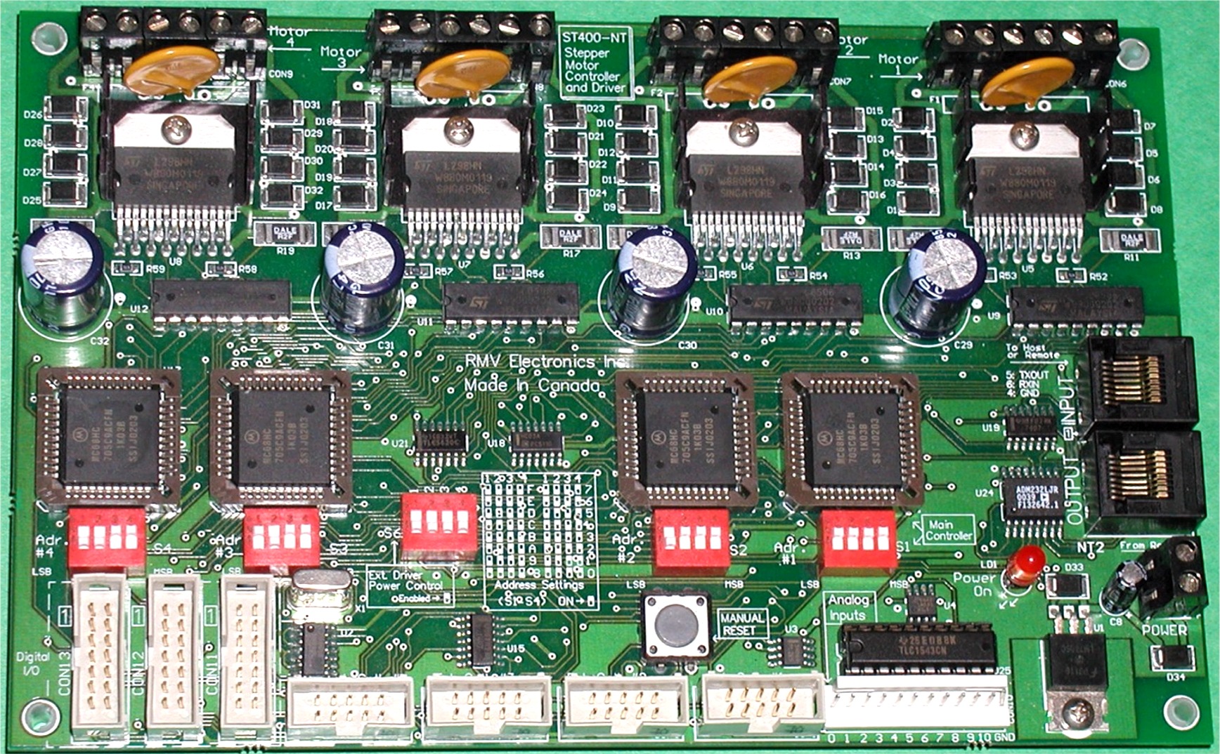
With four on-board drivers, the ST400NT will work with practically any stepper motor up to two amps and 45 volts at
a step rate of between 16 and 8,500 steps per second. The ST400 Series can operate in full step mode, both monophasic
and biphasic, and half step mode. The boards also support acceleration and deceleration capabilities. Inputs for
abort, home,and limit give the user the freedom for sensing motor home, limiting excursion and aborting the motion
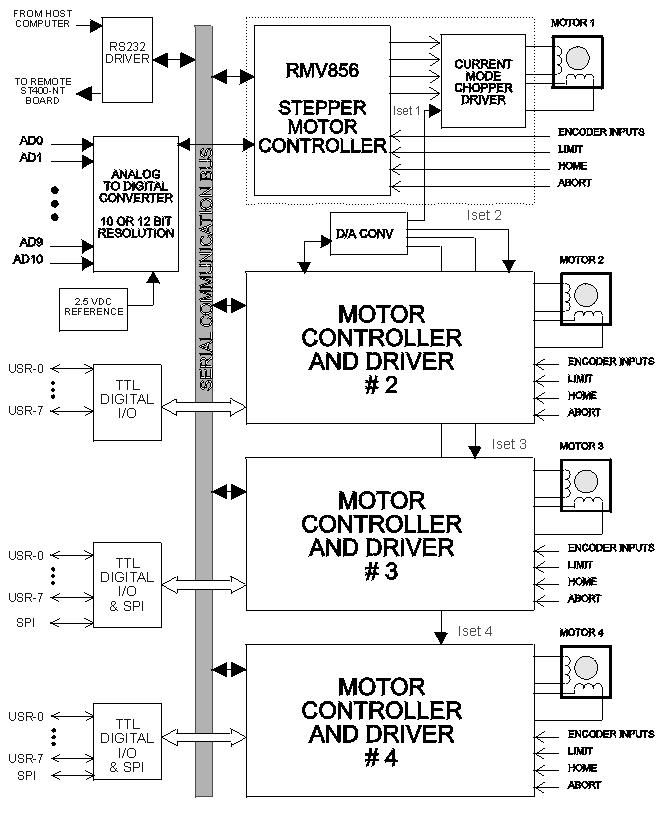
with an emergency switch. Incremental encoder inputs are available for each axis for closed loop control applications
allowing position feedback A stall detection feature controls the positioning error and stops the motor if the valid
position change is not received from the encoder. The ST400NT board also provides control of the winding current on
each motor. The operating current can be set at any value between .1 and 2 Amps under software control trough a \
DAC(8 bits). This allows the user to keep both power consumption and heat generation to a minimum, while the motors
are idle, by reducing the winding current. Smooth motion and higher torque is achievable at high speeds thanks to the
velocity profiling mode, which allows the creation of custom speed profiles using the internal FIFO ( 128 bytes) on
the RMV856 stepper motor controller.
Not only does a single ST400 Board provide sequential or simultaneous control for up to four stepper motors, but also offers data acquisition and control capabilities. Standard on each ST400 Board are 11 analog channels with 10 or 12 bit analog to digital conversion, and 26 TTL compatible digital I/O lines. This greatly extends the functionality of the product, enabling the movement of the stepper motors to be interfaced to analog or digital inputs or digital outputs.
Development of applications for this product is greatly facilitated by a comprehensive, 32 bit Dynamic Link Library (DLL) which provides easy access to all of the ST400 board's many functions. This DLL which allows easy interfacing to Windows based programming languages, employs easy to remember commands such as 'MotorGoToAbsolutePosition', 'MotorPause', MotorTrigger' and 'MotorStop'.
Custom applications can be quickly developed and tested using these simple yet powerful functions. The creation of custom applications is made even simpler by a number of software examples provided for a number of popular high level programming languages.
| Half Step Modes | Full step (monophasic and biphasic) and half step modes |
|---|---|
| Control | Simultaneously control up to 16 stepper motors through a single serial port (network capabilities) |
| Velocity Control | Linear acceleration and deceleration, Velocity profile mode |
| Independent Axis Control | Limit, Abort and Home inputs for each axis |
| Feedback Input | Incremental encoder input |
| Output Control | Maximum 2 Amp chopper driver control |
| Current Control | Individual current control for each motor via software |
| Improved Performance | Torque compensation for improved performance |
| Analog Channels | 11 analog input channels |
| TTL Compatible | 26 digital I/O (TTL compatible) |
| SPI Interfaces | Two SPI interfaces for control of external devices |
| A/D Converter | A/D Converter with 10 or 12 bit resolution, 2.5V reference |
| High Speed Interface | High speed serial interface |
| Smooth Movements | Internal FIFO for smooth movements ( ideal for linear or parabolic interpolation) |
| Dynamic Library | 32 bit Dynamic Link Library (DLL) |
Up to four ST400NT boards can be networked in a single system with 16 stations (four controllers per board). This network can include a maximum of 104 TTL I/O lines, 16 SPI interfaces, and 44 analog input channels.
A single RS232 (serial) port on a PC or host controller can control the system. The RS232 link can be extended as far as 300 feet and each ST400NT board can act as a repeater for the RS232 signal. Individual addressing of each controller is provided through on-board switches for fast network expansion or swapping of individual boards.
The host can address a message to any number of stations in the network. This allows easy synchronization for complex motion control over the entire network.
| Serial Interface: | High speed serial port interface from 9600 to 115200 baud. |
|---|---|
| Stepper control | Step speeds from 16 steps/sec to 8,500 steps/sec. Linear acceleration and deceleration capability. Full (biphasic and monophasic) and half step modes. Incremental encoder input for closed loop control. Current mode driver (chopper) up to 2 Amps/ 48 V |
| Analog channels | 11 analog channels for readings with a range of 0 to 2.5 VDC. 10 KOhm impedance. |
| Digital I/O Lines | 26 digital I/O lines, TTL compatible, can sink/source up to 10 mA each. Two SPI interfaces (3 wires each). |
| A/D Converter | Analog to digital converter with input multiplexer and 10 or 12 bit resolution. |
| Connectors | Cage clamp terminal blocks provided for power and stepper motor connections. Two RJ45 connectors for serial interface. IDC connector for user I/O and male locking headers (.1") for analog inputs. |
| Power Requirements | 7-24 VDC for logic. 5 - 48 VDC for motors. |
| Physical Characteristics | Dimensions (approximate): 19.7 X 12.7 X 2.5cm (7.75" X 5.00" X 1.00") Weight (approximate): 300 grams (10.5 oz). |


